
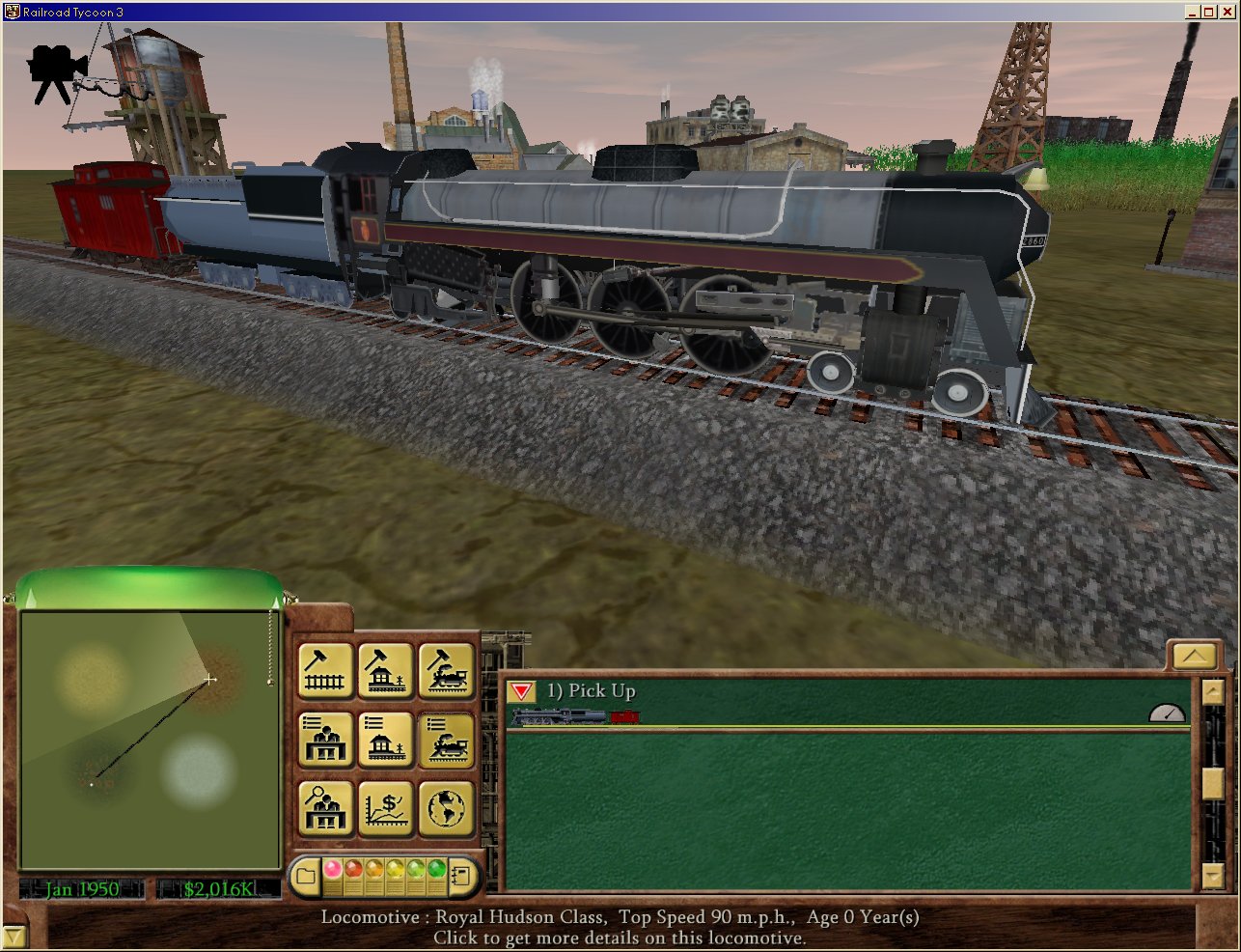
I had a brief exchange with Bombardiere a couple of weeks ago, about how it might be possible to change the region of the skin file that gets painted onto a component. Specifically, I'd been working on the Royal Hudson's skin, and found that the BoxD_truck2 is a good fit for the rear truck, but it uses the wrong portion of the skin file. Part of the side of the boiler shows on the truck, which means that there is no way to make it look like a truck, without making the boiler look wrong too. Plus, I determined that the Pacific's tender is the right size, but it applies the tender side skin as the roof of the tender, resulting in lettering across the top!
Bomber suggested that there is a way to hex-edit the 3DP file to get it to use a different region of the skin, and that he had gained that knowledge from pJay in years past. I haven't heard from him yet, to learn more specifically how to do this, so I am wondering if anyone else knows how.
If it takes some enticement to get you to help me out, I'll dangle this carrot:
http://wpandp.com/royalhudsontemp.jpg
This is an early screenshot; I've done more work on it, but I don't want to release it yet, until I can figure out a way to skin it properly.
A related question:
It would be possible to create unique cars and engines if we could somehow reassign the skin that gets used for a given CargoModel. By taking one Body.3DP and combining it with another Body that has been renamed to CargoModel.3DP, then using a lot of alpha-channel trickery to make parts of each invisible, one should be able to splice things together. I toyed with this while making my Iron Ore Hoppers; the roof of the ChopB body would have made a good-sized heap of ore, within the StockB body that I used. However, I could not find a way to prevent the ChopB portion from getting skinned with the CargoModels skin file (the whole file). Another potential use of this technique (if engines can be assigned a CargoModel that is) is to create an SD40-2 by splicing the GP-35 hood and cab with the SD90-MAC's running boards and trucks.
So, the big question is, how do we re-map a skin file?
Remapping skin file onto car/loco components
Remapping skin file onto car/loco components
=Winchester, Paston & Portsmouth=
====== We Provide Pride! ======
====== We Provide Pride! ======
-
bombardiere

- Dispatcher
- Posts: 425
- Joined: Tue Nov 14, 2006 9:07 am
- Location: Turku, Finland
Re: Remapping skin file onto car/loco components
Sorry Mike. My week has been so hectic. I promise that I explain how it is possible adjust skin on small item such as wheels. (hopefully sometimes before summer...)
Mixing different bodies... No. For this we would need full 3D program and converter. And our RRT3 group doesn't have anyone with that kind of skills.
Mixing different bodies... No. For this we would need full 3D program and converter. And our RRT3 group doesn't have anyone with that kind of skills.
Re: Remapping skin file onto car/loco components
I know about the prohibition against changing the 3D models; what I was suggesting was a way to get around this limit. Each engine and car is built out of multiple components, and one way to "beat the system" is to substitute a Body.3DP file for one of the other unused components. In the case of wagons/cars, this can be the CargoModel.3DP, since not all cars use this component - those that don't can be given a CargoModel nonetheless, and that CargoModel could actually be the Body of another car (or engine). Then, it just comes down to skinning to get them to look like they belong together.
Perhaps for Engines there might be a way to use a second body (call it Body2) as a replacement for one of the Bogies, although I wonder if simply calling it a Bogie would make it roll or spin around - I think you might have told me that you saw this happen once.
The other way I thought it might be done is to use an engine (Body1) and a tender (Body2), and just set the length point to be nearly zero so that they mash together. However, the car following the tender would also mash in, and I don't know what to do about that. Plus, you'd probably see them break apart as the train went around curves - only if you had lengthpoint=0 would they stay tangent at the same angle. Maybe (big maybe here) it is possible to set Body1's lengthpoint to be NEGATIVE, by hex-editing the LP file, and leave Body2's LP to its ordinary value. This would push Body1 back over onto the space occupied by Body2.
Just a bunch of thoughts. Thanks for all your pioneering effort, Bomber, in figuring out what can really be done within the limits of the game. I'm just wondering if there might be even a little bit more that we can do.
=Winchester, Paston & Portsmouth=
====== We Provide Pride! ======
====== We Provide Pride! ======
-
bombardiere
- Dispatcher
- Posts: 425
- Joined: Tue Nov 14, 2006 9:07 am
- Location: Turku, Finland
Re: Remapping skin file onto car/loco components
Well in theory that could be done, in practise it is impossible. I can change wheels, because I can manually identify sections in the code, which relate to the skins. It is doable in wheels, because those contain only few lines. Same principle applies to bodies, but these have thousands bit of codes. it is practically impossible to identify right code without 3D programs.
P.S. I haven't forgotten Royal Hudson. I will get back to you. However, please keep asking your questions. I will try to do my best to reply to you, but my other commitments take most of my time. Your work is greatly appreciated, even if I don't have to fully enjoy your reations.
P.S. I haven't forgotten Royal Hudson. I will get back to you. However, please keep asking your questions. I will try to do my best to reply to you, but my other commitments take most of my time. Your work is greatly appreciated, even if I don't have to fully enjoy your reations.
Re: Remapping skin file onto car/loco components
Bumping this thread. I still don't know how to reassign a truck and wheel to a different portion of the skin file, and it bugs me because this is all that is standing between me and a finished Royal Hudson.
Bomber, Milo, anybody else know how to hex-edit a truck/wheel 3DP file?
=Winchester, Paston & Portsmouth=
====== We Provide Pride! ======
====== We Provide Pride! ======
Re: Remapping skin file onto car/loco components
Thank you Bombardiere!
He found his hard copy of the notes from Pjay on the 3DP file format, and there is enough info in there to deduce how to determine the skin file coordinates for a given triangle, and those coordinates can be easily changed.
Okay, maybe not really easily. Simple elements, like a wheel, have only a few triangles, so it is easier to figure them out. An engine body has a slew of triangles... and the 3DP's have "instances" which repeat some but not all of the triangles and their coordinates. Thus, it would be much more difficult to remap elements that are part of an engine body, or any other complex shape.
I will post a better graphic explanation of what needs to be changed, but I wanted to clarify something that (it seemed to me) even Bomber didn't fully understand about the coordinates. They are listed as pairs of floating-point numbers for each of the three vertices of a triangle; two triangles together make up a rectangular face. Thus, towards the end of the file you'll see a section that looks like:
... 04 00 00 00 _ 06 00 00 00 _ 07 00 00 00 ...
(which signifies that this is the triangle formed by points 4, 6, and 7)
then
... AA BB CC DD _ AA BB CC DD _ AA BB CC DD _ AA BB CC DD _ AA BB CC DD _ AA BB CC DD ...
(which lists 6 coordinates, 4 bytes each, as X,Y for the first point, X,Y for the second, etc.)
What I did is to map out which coordinates belonged to each point, as the source file and the destination file might use a different point order for their triangles. You can't just cut and paste the whole list of coordinates; rather, you need to type Point 4's coordinates wherever point 4 is listed in the file. If you don't you will get skins that look very warped and stretched.
Using my favorite hex-to-decimal converter, I typed in a few of these coordinates and discovered that what they are is percentage values. In other words, if Point 1 has an X value of 0.51, then it means that it begins at the pixel that is 51% across the skin, going left to right. The Y value is the same, going from the top down. So, if you have a new wheel that is located between pixel 324 and pixel 438 (X) and between pixel 26 and pixel 140 (Y), and the skin file is 512 pixels in each direction, then the coordinates you'd supply for the four points on the two triangles would be 324/512 = 0.633, 438/512 = 0.855, 26/512 = 0.051, and 140/512 = 0.273. Of course, you need to translate all these numbers to hexadecimal.
Incidentally, I don't think anyone has mentioned this elsewhere, but the byte order in all the RRT3 files that I have worked on, when it comes to floating-point numbers, seems to be reversed from what it should be. Whenever I use my hex-decimal converter, if I type in what is in the file as "AA BB CC DD" then I get some weird result, but if I flip it and type in "DD CC BB AA" then it comes out fine. This is true for the coordinates as well.
=Winchester, Paston & Portsmouth=
====== We Provide Pride! ======
====== We Provide Pride! ======
-
bombardiere
- Dispatcher
- Posts: 425
- Joined: Tue Nov 14, 2006 9:07 am
- Location: Turku, Finland
Re: Remapping skin file onto car/loco components
Great!!!!!!!!!!!!WPandP wrote:
Using my favorite hex-to-decimal converter, I typed in a few of these coordinates and discovered that what they are is percentage values. In other words, if Point 1 has an X value of 0.51, then it means that it begins at the pixel that is 51% across the skin, going left to right. The Y value is the same, going from the top down. So, if you have a new wheel that is located between pixel 324 and pixel 438 (X) and between pixel 26 and pixel 140 (Y), and the skin file is 512 pixels in each direction, then the coordinates you'd supply for the four points on the two triangles would be 324/512 = 0.633, 438/512 = 0.855, 26/512 = 0.051, and 140/512 = 0.273. Of course, you need to translate all these numbers to hexadecimal.
I have done the same, but I didn't realise that these are percentages!!!!!!!! How stupid of me
Yes we have noted it a long time ago (Pjay, Chris, Milo et al.) so I have totally forgotten it is a wrong way. Just like living too long in the UK has made me thinking that driving on left is natural thing to do....Incidentally, I don't think anyone has mentioned this elsewhere, but the byte order in all the RRT3 files that I have worked on, when it comes to floating-point numbers, seems to be reversed from what it should be. Whenever I use my hex-decimal converter, if I type in what is in the file as "AA BB CC DD" then I get some weird result, but if I flip it and type in "DD CC BB AA" then it comes out fine. This is true for the coordinates as well.
Re: Remapping skin file onto car/loco components
Okay, now that I know how to remap the skin file onto a model's triangles, I might know just enough to be truly dangerous!
I used this info to successfully combine multiple car bodies into one; please see my Covered Hopper for Grain car, the Z model. By taking the HopD body 3dp file, and naming it as Truck3, I ended up with hopper bottoms under the StockCar body that I used as my basis. However, to make this work, I had to make everything but the hopper bottoms invisible... by remapping them onto a transparent corner in the skin.
Bomber had suggested that simply hex editing the skin file vertices to "00 00 00 00" each that the triangles would become invisible, but this is not what I saw happening. Instead, I got solid colors (that changed at night!). So, I had to remap the triangles to a 4-pixel area at top left corner - zoom in on my BN Chop and you can find this hole in the corner of its roof!.
To make this remapping simpler, I reduced the INST count from 5 to 1, and deleted most of the 3DP file. Had I been a little smarter, I'd have isolated it down to the particular INST which included the hopper bottoms but not much else; each successive INST has fewer polygons, and at the lowest level, even the hopper bottoms are not modeled. I used INST #1, but my guess is that probably INST #3 could have been used, and then I would not have had to remap as many triangles.
The trouble with all of this is that it is EXTREMELY TEDIOUS to map out which vertices describe which triangles, then convert pixel# to decimal to hex code for each coordinate. This is what we need a decent 3DP editor for; it wouldn't have to be a 3D modeling tool, necessarily, but even just something that could display all the info within the file in an orderly manner and handle all the hex conversions on the fly... perhaps as a spreadsheet.
=Winchester, Paston & Portsmouth=
====== We Provide Pride! ======
====== We Provide Pride! ======